The Tanks Are Shot!
The boat was built in 1980. Now it is 34 years old. The fuel tanks on almost all the 80's trawlers out of Taiwan were built out of mild steel. Some people refer to this as "Black Iron". If kept dry, inside and out, the tanks can last for a very long time, If moisture is allowed to get inside the tank through condensation or more likely a old o ring on the fuel fill, or bad fuel, the tank can rust from the inside. If the teak deck sealant is not maintained, water can follow the deck fill tube, pool on the top and rust out the tank. Anywhere a tank touches wood moisture can collect and rust the steel or corrode aluminum.
The original tanks were painted, then set on a hardwood plywood platform.A frame was built out of mahogany and the structure was covered in plywood and acoustic tile. Below is a picture of the structure with the acoustic tiles removed. This made it very hard to access the tanks to inspect, survey or maintain them. Many owners just ignored with they could not see. Many surveyors do the same.
If you are buying a old boat with steel tanks, find a way to inspect the tanks. I pried open the plywood on one end. Other ways to look include, under the settee, in the salon, there is a hole for the fuel fill tube. You can see the top of the tank there. I reached down and felt rust and holes in the tank. In the galley, if you remove a plywood panel behind the refrigerator, you can see the deck fill tube and the tank below as well. I actually brought up grass growing on top of the tank. This changed the purchase price substantially. The Albin owners blog helped me to understand the scope of a DIY tank replacement. Some can do it others should find another boat!
Using a sawsall, I cut away the plywood covering the tanks. They used mahogany ply and attached it with ring nails pounded into mahogany rough cut lumber. This made it difficult to remove.The carpentry was elementary. In my opinion, your not gonna be able to save any of the ply, its diesel soaked, smelly and needs to go, so just rip into it with the big stuff. It will save you time.
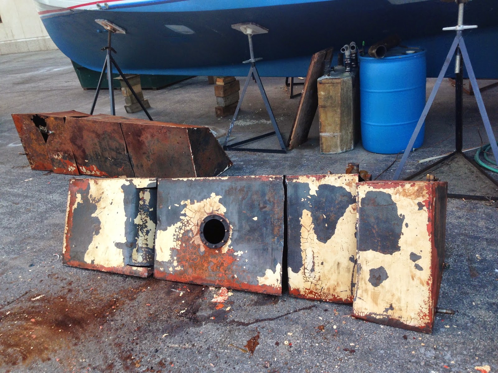
Interesting to find a inspection plate on the tank. It was completely covered up and never used. Who would know? Now USGC rules prevent inspection plates anywhere but on the top of a tank. Now tank manufacturers use epoxy to coat aluminum. This old paint is most likely lead based. Use a respirator! Most of it came off with just the shop vac.
That stove pipe is the exhaust pipe. A shop vac stripped the flaky paint off. No primer, wrong paint.
Next Step, remove the engine. I had several reasons to remove the engine, but it would be impossible to remove and replace the fuel tanks with the engine in place. here is a link to that process.
Link to removing the engines post
In the blogs/forums, many people removing tanks commented that they went through many carbide blades and one even said he burned up a sawzall cutting up the tanks. I used the blades above. It took three blades for both tanks. I let the saw do the work and it cut through like butter.
It gets a little tricky getting into position to make all the cuts. Be careful as the cut edges will gouge the salon woodwork or slice you wide open, wear gloves, long sleeves heavy with material.
I cut each tank into 4 pieces to make it easier to remove. The starboard tank was the worst. completely rusted!
Yes that's a hole around the deck fill
Holy Neglect batman!
This shows the plywood under the tank. They attempted to keep the tank off the wood using three strips of foam material. It did not last. The fiberglass in the hull is about 1/2 to 5/8 thick. No gelcoat on the inside, so it lets the light through.
I took measurements of the tanks before I cut them up. They were custom built just for this boat. They were irregular and each tank was unique. This will frustrate the replacement manufacturer later. I made mock ups from the measurements. There are two important reasons. One, to make sure I could install the tanks. I already removed the engine to rebuild the bilge, making this possible. Second to make sure my measurements are correct and to be able to make any changes needed.
Replacement Fuel Tanks
After much research, I decided to go with custom aluminum tanks of the same size as the original.
This is a coastal cruiser, a great looper or even a Caribbean cruiser. I want the range. If I ever get the time and money to cruise, I want to be able to take advantage of low fuel prices and get fuel from trusted sources.
I got the fuel tanks from Atlantic Coastal Welding
Speedytanks.com I got three quotes, they were competitive, my marina had used them before and they were mentioned in many blogs/forums. They were great to deal with and really made them, shipped them, delivered the tanks in 7 days. They were just what I had ordered.
With plastic, I could go smaller which would serve 90% of my cruising needs. That would give extra room in the bilge as well. Plastic lasts forever and is a great option for some. Plastic cannot be purchased custom built, unless you want to pay for the molds at $5K each, plus the tank. You have to choose from existing designs. I could not find a design even close to the size I needed. I could build my own custom tanks out of fiberglass. That option would be much less expensive but would take a lot of time to learn how to build one.
In the end, it was the design of the tanks that helped me make my decision. The original design slopes down to the stern corner where the equalization port is located. (This is a tube between tanks that keeps the fuel level in both tanks.)
The sloping sump design means that as the fuel is consumed, the volume of the tank used also reduces. This gives less ares for sludge to accumulate and a direction for it to go. Locating the fuel pick up near the bottom of the lowest point will allow any build up to be picked up as it is created and removed to be picked up by the filters.
I can adequately manage a lot or a little fuel so I can burn what I have keeping the fuel fresh. In my opinion, keeping fuel tanks full to eliminate condensation is a myth. Water gets into fuel from the fuel vendor, and from leaky o rings in the fuel fill. If you keep the amount of fuel to a minimum, the pick up will pull water into the water separator as needed.
A good dual filter system with pressure gauges helps to manage this. A good idea is to add an extra pick up and return located on opposite ends of the tank. That will allow for fuel filtering (polishing) while under way. Add a small day tank and filter all the fuel out of each tank when they are low at least once a year.
Here is a detail of how the filters work:
Back to fitting the mock ups.
They fit in the port door!
Now to see if they fit down into the bilge.
Next, testing the template in place. This was actually the second set of templates used. The original measurements did not quite fit the space well. I made adjustments and needed new templates. I used cheap 1/4 ply and 1 X 2's to make the mockups. I found each tank space unique and not symmetrical. Boat building is a bit of an art. Not really rules, more like guidelines! Arrrrr...
Here is the new work space. I bit the bullet and paid for inside heated storage this winter. The goal is to get her in the water to finish the exterior work. This winter it will be the patch the hull, install the tanks, fix the bilge, and rebuild all the windows.

Well the tanks arrived from Atlantic Coast. They were amazing to deal with. From the time we agreed on the plans, they built and shipped them to WI in 7 days. They advertise a 5 day build and they did it in 3. The shipping only took two days. Total cost for everything with the epoxy coating was a little over $4000. Now to prep the hull and make a new support structure. Looking back, I should have taken many more measurements of how the old tanks were installed, but on the other hand, they were not installed correctly. All the weight of the tanks was on one teak block used to wedge the tank in place. The teak block was held in place by one ring nail that split the block. amazing it lasted 35 years. Just above the nail sticking in the frame you can see the block. It is holding the tank off the plywood base. That's one way to keep it moisture free!
This is the before shot
This is the after. I decided not to paint the bilge. Four coats of old paint tells me paint doesn't last. I do not want to have to clean, scrap, strip prep and paint every few years. So I decided to gel goat the entire bilge. It takes a lot more prep work to get the surface ready, but this is the last time it will have to be done. Scrub with soap and water and its new again.
I used 3/4 Douglas fir marine grade plywood. I coated it with epoxy. In my opinion, you can get away with Home Depot type plywood but why not use a rot resistant species made with water proof glue. I don't want to do this again in 10 years. I am building for 30 year life cycle.
The fork lift raises the tanks to cabin level. Then, myself and two of the great guys at Southport Marina helped wrangle the tanks in the port door, and down in the bilge. They fit just like the mock up, but heavier!
This next task was to install the neoprene on the bottom of the tank. In hindsight, I would have done a dry fit of the tank after building the tank base. 5200 takes 2 weeks to set up enough to support the weight of the tank on the slanted base. Especially in the 50 degree building. Better than the early freeing temperatures this year!
This idea is to support the tank on the neoprene pads. They were placed 8-10 inches apart. Anywhere the tank comes in contact with anything, it should have a neoprene pad to prevent moisture from coming in contact with the tank.
I used white oak lumber to build up the frames to support the plywood base for the tanks. This was the hardest part of the project so far. With the plywood in place, I measured the space in between the frame and the plywood. The tank and plywood are flat, the hull is not. I used a wedge shaped piece of wood, shoved it in between the ply and frame in three places on each frame.
I reached under the plywood with a pencil to mark the spot on the wedge. I used the three measurement to make a cardboard template. Once the template was correct, I cut out the oak piece. I then screwed each support of oak onto the frame and screwed the plywood on the supports. Its very solid and will displace the weight of the tank on the hull.
Finally the fuel senders were installed and the tanks were moved into place!
I used white oak lumber to build the hold downs for the tanks. I bolted them to the "frames" in the hull and to each other, that way the tanks can be removed with out much trouble if needed.
I used 5200 to attach neoprene strips to the oak in any location near the tank. The aluminium tank is suspended on the neoprene pads and doesn't touch any wood. This will avoid deterioration of the metal in the future.
Final installation. Now time to design and install the fuel management system.