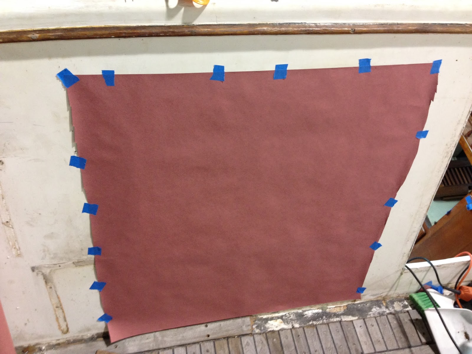
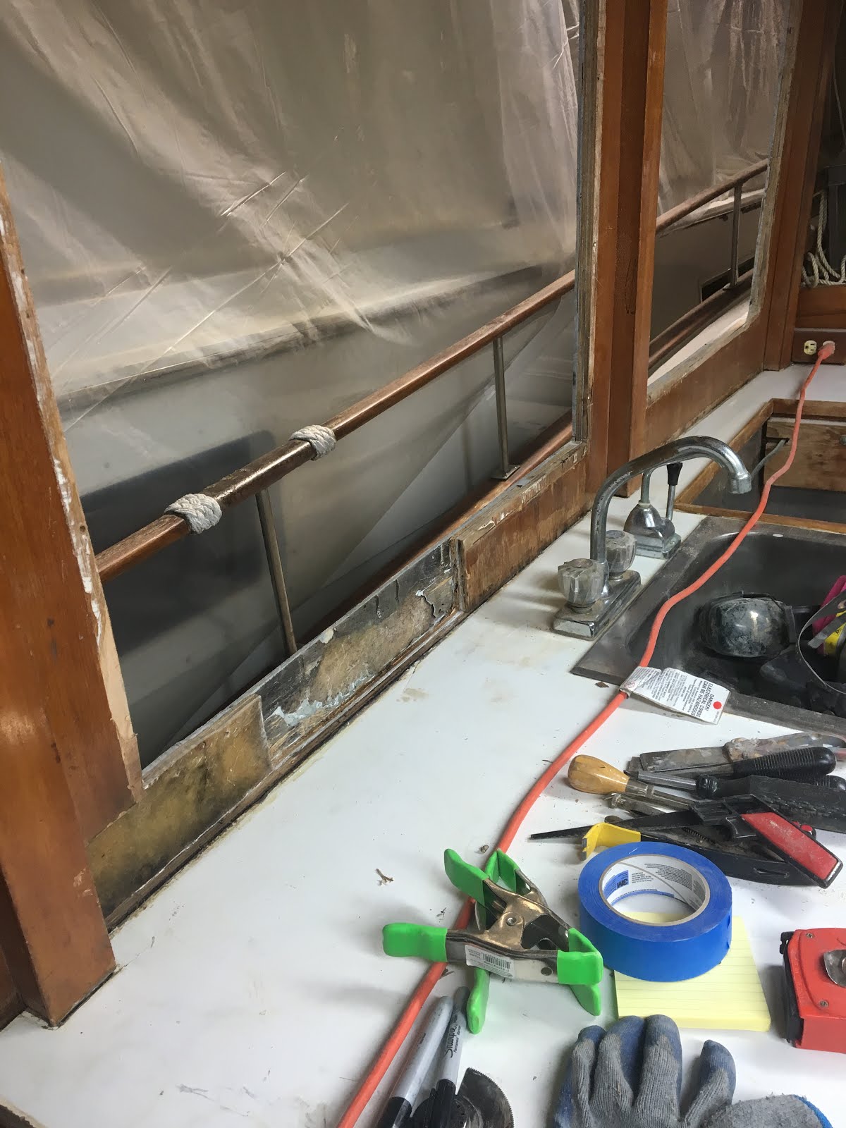
Page under construction, Stop back in to check up on progress.
Tip of the Iceberg!
Warning: For those of you that have a Taiwanese made trawler that has the beautiful teak windows you may not want to read this post. It may be better to stay in ignorant bliss and tell yourself that your slight leak may have affected only the veneer. A little sanding, varnish and silicone and volia! problem solved. You may also wonder where that tea colored water in the bilge comes from when it rains. The bilge pump takes care of it. Maybe your boat has an odor you attribute to the sanitation system. All could be symptoms of water damage in the walls.
The refit of Tortuga has tested me I will admit, but until now, I have always thought I was the unique person that could have a better boat for less money via the DIY route. I am half way through what started out as a window project. I thought, pop off the outside trim, re glaze the windows, a few new bungs and varnish and then address the damaged veneer inside and I'm done. It did not work out that way. Moisture meters are a joke! I now have come to the realization for the first time that I may have a much bigger project than I imagined.

This is the first window I started on. Its on the stern wall of the owners cabin next to the exit hatch.

The trim and glass came out first.

I used an ice pick and 1/4 inch chisel to remove the old bungs. Sometimes a 1/4 or 3/8 forstner bit works as well. Its maddening when you find the PO used glue or worst epoxy to seal a bung. Very hard to remove. This is slow process. The screw heads are exposed and the screws removed. I used a screwdriver and an impact driver. Once you get good at it, an impact driver world very well, but it can and will tear up screw heads. Sometimes as careful as you are, the teak just wont let go and the screw heads twist off. If that happens, don't panic, drill them out oversize, fill with epoxy, re drill to pilot size.

I used my multi tool with an 1 in metal/wood blade to dig under the trim and cut the old polyurethane caulk. This type of caulk cannot be pulled apart, it is too strong and the wood, even teak will give first and break. You have to mechanically separate all the caulk with the blade of the multi tool. If the multi tool is set too fast, it will heat up the caulk and bog down.
First go around all the edges of the trim and cut out 1/4 inch of caulk, then take out another 1/4 inch. Next I plunge the blade all the way though the caulk under the trim until I can see the bade out the other side. Then, I clear out about 6-9 inches working from the outside of a piece to the middle. Next, I insert a screw driver and carefully pry the trim away from the wall. If you put too much pressure, the teak will break.


Glass in the rabbit
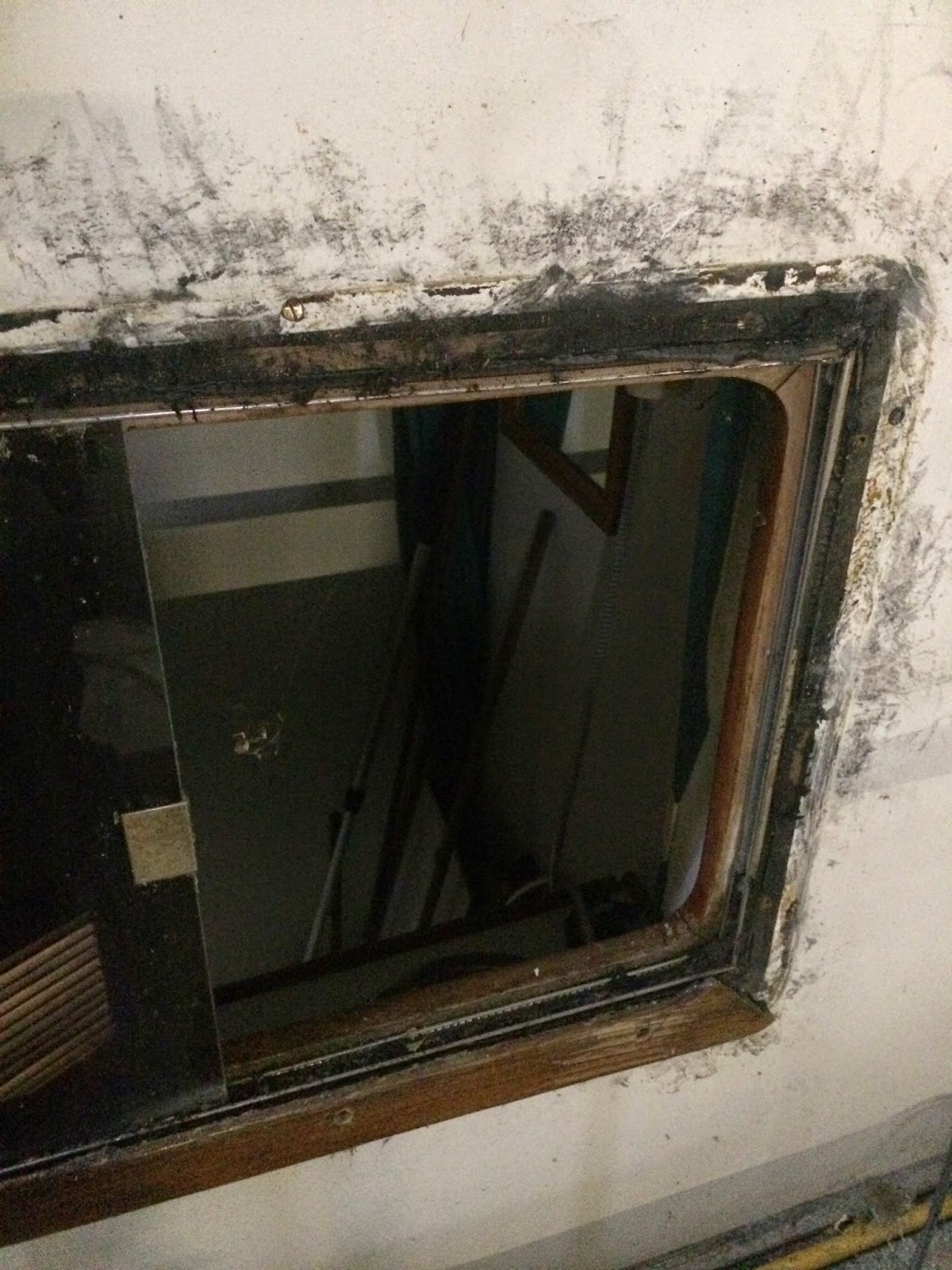
Top and right side trim removed. The caulk makes a mess.

The inside and outside trim on the workbench for clean up
The inside trim has a rabbit cut for the laminated tinted glass. This was screwed into the cabin wall. They used black polyurethane (5200) or poly sulfide caulk. It is a very strong adhesive but not the best sealant. I found uneven distribution of the caulk. The windows probably started leaking 4-5 years after being built. A better but more expensive system is aluminum framed windows. Taiwanese trawlers usually choose the cheaper easier route.
When the original varnish needed its first re finish job, they should have removed the trim and re caulked with a caulk that is less adhesive and seals better. I like butyl tape for long straight flat runs and life caulk for larger uneven areas,
Two things prevented most owners from doing this. One, there were no obvious leaks so why go to the trouble. Most owners are not comfortable removing bungs or re finishing varnish. Two, if they did try to remove the trim, it would have been very very hard to do. In 1985, they did not have a multi tool yet. Most owners waited for trouble then went with silicone on the exterior.
Once you remove the trim you have a hole cut on the wall. The wall has 4 parts. The first is an outside gelcoat with fiberglass laminate made in a mold. Next is a mahogany plywood core. They used a strong putty to attach the patchwork plywood to the laminate. This is encased in another layer of fiberglass laminate. The third layer is interior mahogany plywood. Finally after all of this was installed they glued veneer to all the interior surfaces.
Ring nails were used to attach the interior ply to the laminate. The ring nails were found under the veneer. This surprised me as around here we generally apply the veneer before installation on the boat. They way they did it allowed for economical placement of the plywood. When the window was cutout, their was NO resin or sealant applied on the exposed edges. This is a huge oversight providing no back up for caulk failure. If the caulk failed, water will travel into the plywood in every layer, period!
Here are some pictures of the interior looked like.

Tortuga's owners cabin when purchased.


Damaged veneer on the port side window.

Damaged veneer under the Port Portlight. There was silicone all around the window.

This area looks OK, not too bad on the outside.

On the inside of the owners cabin I removed a horizontal piece of trim and found rot in the veneer and plywood behind it. This extended from port to starboard.

Next I removed the horizontal plywood under the deck. It was rotted and moldy. Looking from the bed up at this area you can see the under side of the aft deck. Notice the veneer looks good except under the trim area.

Water damage to the inside veneer and plywood on the door

Next I removed the door trim. This exposed significant rot extending to the plywood surrounding the door,

The wall construction layers can be seen along with water intrusion damage. The upper corners seemd to be sealed poorly.

Looking up at the damage.

ON the other side the damage extended to the ceiling plywood as well as the veneer and ply on the wall.

Once the trim was removed, it got worse. Now the damage to the wall was so extensive, I decided the interior ply and veneer had to come out.

With the port light removed, the damage to the plywood was extensive.

The ply had to come off.

As each section some off, the damage to the ply indicated more had to come off as well.

Eventually the entire stern and Port interior layer had to come off. This shot also shows a yellow color to the laminate. in the upper right it is darker. I used a ball peen hammer to test the wood finding the yellow laminate had separated from the ply due to freezing of water which had intruded from the doors and window edges left unsealed after the caulk failed. Yes this means the laminate and the core have to come out too!!

Stripping off the laminate

Rotted ply under the lamanite was attached to the outter skin with some very tough type of putty. The plywood was not attached with resin and FG. Another short cut allowing water to spread unchecked.

They used scraps of plywood using the putty to fill the gaps. A hole was drilled in each piece with putty injected. This may have been to hold the board in place for the lay up of the FG. There was mold and green moss growing in here. All passed the moisture meter from the surveyor. This is years of water intrusion.

This shows the process, remove the skin, chip off the putty with an air chisel, sand down to clean glass. I am going to restore this wall before I tear down the port wall to provide support to the roof.
More to come, The fun never stops. So much for a launch this spring,,,,,,,,